E ovako da sve lepo objasnim.
Arduino TX -> TX GSM2 Click
Arduino RX -> RX GSM2 Click
Arduino 5V -> 5V GSM2 Click
Arduino GND -> GND GSM2 Click
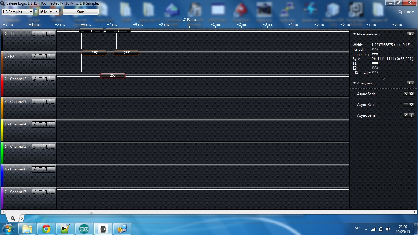
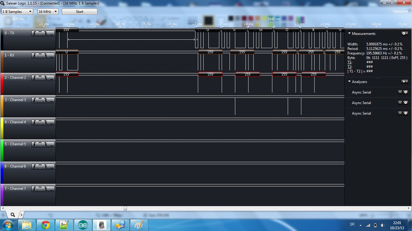
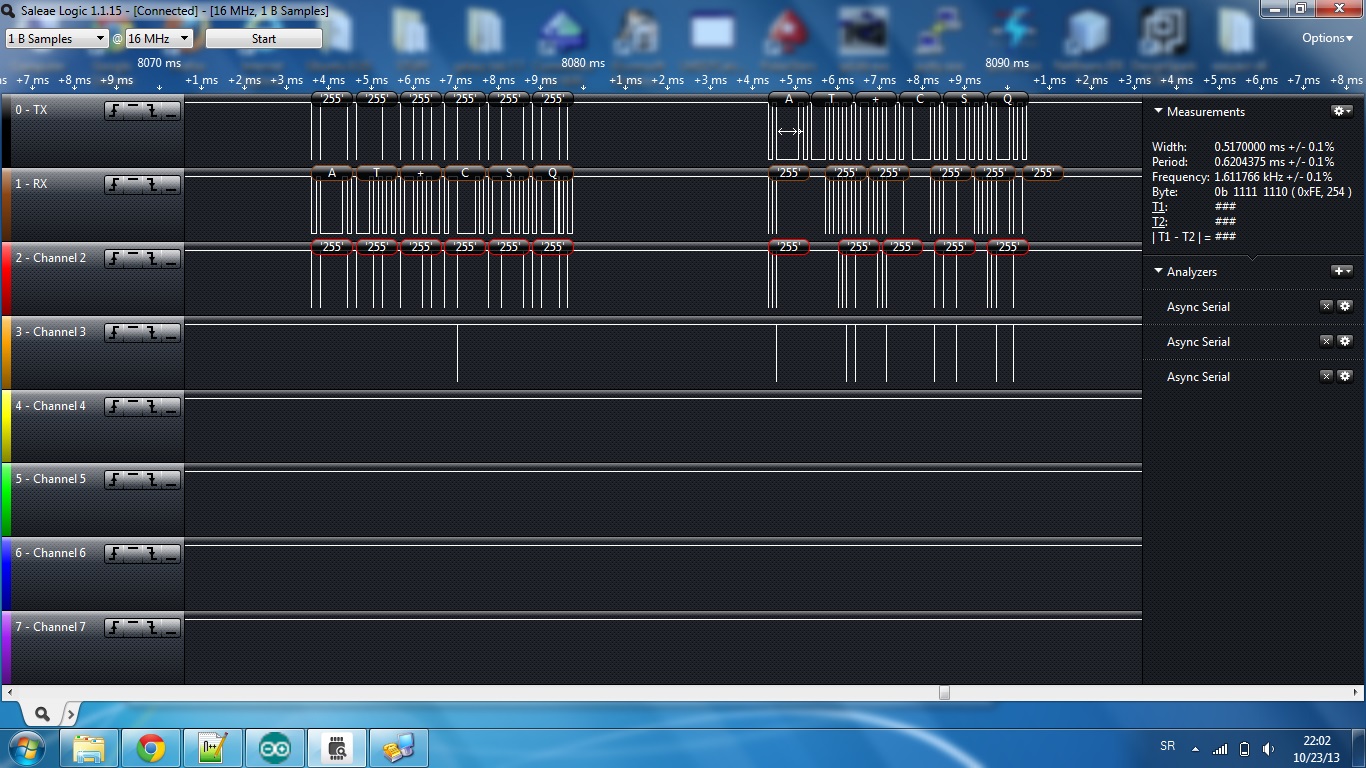
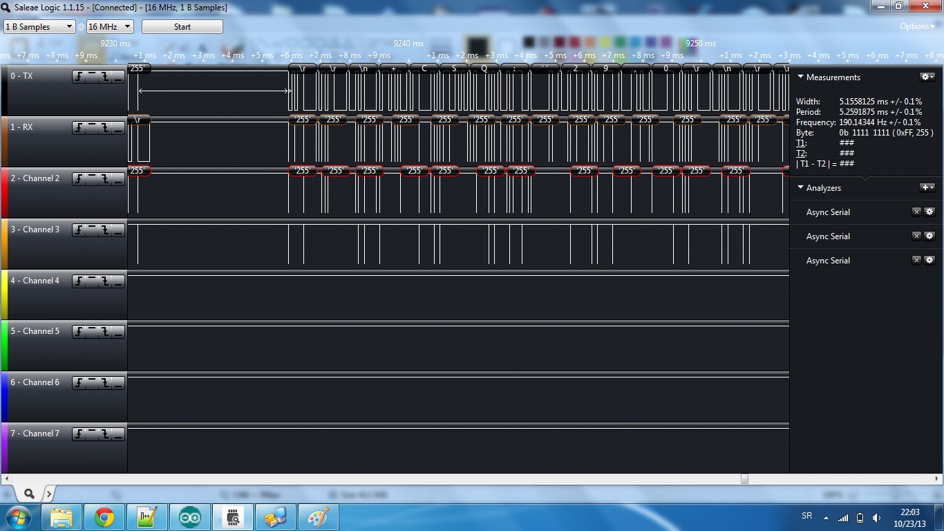
China Saleae loger CH0 paralelno na RX
China Saleae loger CH1 paralelno na TX
Baud rate u Arduinu je 9600, (gsm ima auto) a probao sam i na 19200.
Saljem u prilogu arduino code ako nesto znaci:
Code:
/*
GSM_easy__test.ino - This small software will perform a simple test of the GSM-easy! - Shield
Version: 1.2
Date: 01.01.2013
Company: antrax Datentechnik GmbH
Use with: Arduino UNO (ATmega328) & Arduino Duemilanove (ATmega328)
This program tests the basic functions of a GSM-easy! - Shield:
- Power-On and starting sequence
- SIM-Pin hand over
- registering to the GSM network
- check GSM and GPRS status
- query some infomation, e.g. IMEI, RF signal strength, SIM card operator
Hardware test:
Testing is for use with an Arduino Duemillanove, Arduino UNO or Arduino Mega2560. Only the Arduino mainboard and the
GSM-easy! - Shield that is to be tested are plugged together. Additional inputs and outputs on the Arduino mainboard
should not be connected at this point.
Furthermore an external power supply that can provide at least 9V/1A MUST be connected to the Arduino mainboard.
This is not a suggestion, but an absolute must for the operation of the wireless module on the GSM-easy! - Shield.
The power supply via the USB port is not sufficient!
Software test:
The test software can be found here ---> http://www.antrax.de/downloads...ntrax-examples/gsm_easy__test/
and must be loaded to the a. m. hardware (= Arduino mainboard and GSM-easy! - Shield). After transferring the software
the "Serial Monitor" of the Arduino development environment must be started(with the short key combination Strg+Shift+M
or by using the menu via Tools - Serial Monitor).
The test software does not require a library. The test software does not include time and programmatically optimised
processes and function calls (a test run takes approx. 45 seconds). The test software will test exclusively and in a
comprehensible manner the basic functions of the mobile module used.
ATTENTION: you MUST set your own SIM pin!
Test result:
To see how a correct output via the "Serial Monitor" looks like see here:
http://www.antrax.de/downloads...cols/gsm-easy__test-report.png
Some displayed outputs, for example "+CFUN:1", "+CPIN: ...", "Call ready" may vary in content and position in the
gsm-easy__test-report.png, as this data/reactions are partly provider or SIM card dependent. The hardware of the
tested Shield is working properly if alltogether reasonable reactions are processed on the AT commands given.
Although no actual data exchange/voice connection is executed with this test program, all major functional areas
are tested.
NOTE:
This test software was also used for the "test report" you received with your package. As you can see from the "AT+GSN"
unique IMEI output, a test report is always bound to the mobile module on the Shield.
Before asking ("my GSM-easy! does not work") please always start the test program and check the output in the "Serial Monitor".
We only use basic AT sequences (with the library), for detailed information please see the "M95_AT_Commands_V1.0.pdf"
WARNING: Incorrect or inappropriate programming of the mobile module can lead to increased fees!
*/
// pin definition
#define PWRKEY 4
#define EMERG 5
#define GSM_ON 6
String GSM_string = "\r\n\n\nTest Protocol: GSM-easy!\r\n------------------------\r\n";
//----------------------------------------------------------------------------------------------------------------------------------------------------
void setup()
{
Serial.begin(9600); // 9600 Baud data rate
Serial.print("\r\nStart Test Sequence: GSM-easy!\r\n(Please wait ... appr.45s)\r\n------------------------------\r\n");
}
//----------------------------------------------------------------------------------------------------------------------------------------------------
void loop()
{
//---------------------------------------------------------------------------------------------------------------
// let's power up the shield
// ATTENTION: you MUST set your own SIM pin!
digitalWrite(GSM_ON, HIGH); // GSM_ON = HIGH --> switch on + Serial Line enable
// Init sequence, see "M95_HardwareDesign_V1.2.pdf", page 30ff.
// in any case: force a reset!
digitalWrite(PWRKEY, LOW); // PWRKEY = HIGH
digitalWrite(EMERG, HIGH); // EMERG_OFF = LOW
delay(50); // wait for 50ms
digitalWrite(PWRKEY, LOW); // PWRKEY = HIGH
digitalWrite(EMERG, LOW); // EMERG_OFF = HIGH
delay(2100); // wait for 2100ms
digitalWrite(PWRKEY, HIGH); // PWRKEY = LOW
delay(1100); // wait for 1100ms
digitalWrite(PWRKEY, LOW); // PWRKEY = HIGH
// Start and Autobauding sequence ("M95_AT_Commands_V1.0.pdf", page 35)
delay(3000); // wait for 3000ms
//---------------------------------------------------------------------------------------------------------------
// let's register in the GSM network with the correct SIM pin!
// ATTENTION: you MUST set your own SIM pin!
GSM_string += "Send the first AT:\r\n";
Serial.print("AT\r"); // send the first "AT" for fixing autobauding
WaitAndRead(1000); // wait for 10 seconds
GSM_string += "Set Manufacturers defaults:\r\n";
Serial.print("AT&F0\r"); // Manufacturers defaults
WaitAndRead(100); // wait for 1 second
//---------------------------------------------------------------------------------------------------------------
// let's register in the GSM network with the correct SIM pin!
// ATTENTION: you MUST set your own SIM pin! "1357" is an example only!
GSM_string += "Query SIM status:\r\n";
Serial.print("AT+CPIN?\r"); // query SIM status
WaitAndRead(100); // wait for 1 second
GSM_string += "Enter SIM pin:\r\n";
Serial.print("AT+CPIN=1357\r"); // enter pin (SIM)
WaitAndRead(100); // wait for 1 second
delay(20000); // wait 20s. of registration in the GSM network
//---------------------------------------------------------------------------------------------------------------
// ok, the ME should be registered in the GSM network ... now let's find out all the info and stati of the module
GSM_string += "Query register state of GSM network (20 seconds later!):\r\n";
Serial.print("AT+CREG?\r"); // Query register state of GSM network
WaitAndRead(100); // wait for 1 second
GSM_string += "Query register state of GPRS network:\r\n";
Serial.print("AT+CGREG?\r"); // Query register state of GPRS network
WaitAndRead(100); // wait for 1 second
GSM_string += "Query the IMEI:\r\n";
Serial.print("AT+GSN\r"); // Query the IMEI
WaitAndRead(100); // wait for 1 second
GSM_string += "Query the RF signal strength:\r\n";
Serial.print("AT+CSQ\r"); // Query the RF signal strength
WaitAndRead(100); // wait for 1 second
GSM_string += "Query the current selected operator:\r\n";
Serial.print("AT+COPS?\r"); // Query the current selected operator
WaitAndRead(100); // wait for 1 second
//---------------------------------------------------------------------------------------------------------------
// power-off the ME to avoid any error messages, caused of the Serial.print commands for the monitor
digitalWrite(GSM_ON, LOW); // GSM_ON = LOW --> switch off + Serial Line disable
Serial.print(GSM_string);
Serial.println("--- E N D ---");
while(1);
}
//----------------------------------------------------------------------------------------------------------------------------------------------------
// read function for the serial line
// Parameter: timeout in steps of 10ms
void WaitAndRead(int timeout)
{
for (int i = 0; i < timeout; i++)
{
delay(10);
while (Serial.available() > 0)
{
char inChar = Serial.read();
GSM_string += inChar;
}
}
GSM_string += "----------\r\n";
}
//----------------------------------------------------------------------------------------------------------------------------------------------------

 Arduino and GSM2 Click by Mikroelektronika


 Re: Arduino and GSM2 Click by Mikroelektronika
 , pa ME su uvek bili nekompatibilni sa samom sobom.